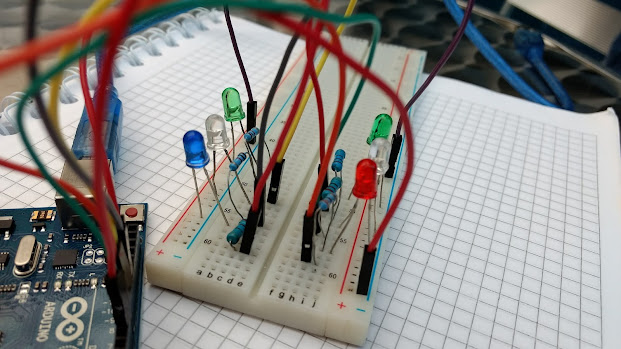
In the last post, we have learned about how to blink a LED using Arduino. Now we are going to make a led blinking pattern using it. LED Knight-Ridder Circuit is that. Let’s get started.
Knight-Rider Circuit
You have to have those things with you for creating this
Knight-Rider Circuit.
- x5 LED
- x5 220ohm Resistor
- x1 Arduino Board
- x1 Suitable Cable for Arduino Board
- x11 Male to Male Jumper Wires
- x1 Project board
You have to make the circuit like this for creating
knight-rider circuit. You have a sense about how we going to create this
circuit now.
We put 220ohm resistors for the safe of Arduino. Without resistors also ok. But it’s better to put them. You don’t need to put 5 LEDs. 3 LEDs are also ok. Also 13 LEDs are ok. You can get attractive output according to LED amount. In this pattern, I’m going to make single LED spot go through the LED raw.
You have to make code like that and upload the code. You can watch the result using above web simulation by pressing ‘Start Simulation’. In the Void Setup I initialized 2nd pin to 6th pin as outputs and in the Void Loop, I blink 1st LED and then turn it off. Next, I put 1 second delay and turn on the 2nd LED. After completing one LED cycle. I reversed it. So, there is a LED blinking cycle and it’s very attractive. You can tryout this at home. This is very interesting Arduino project.
Now this is another pattern of knight rider circuit. I’m
going to make the single LED blink to multiple LED blink. In this patter one
LED is on then 1 second delay, after that 2nd LED is on with 1st
LED. So, that’s a different kind of an attractive pattern. You can see that
pattern at shops. Here is the source code and simulation. Press the ‘Start
Simulation’ to see how this pattern going to work.
Dark-Spot
This is also a different kind of circuit type. In the knight-rider circuit, we make one led blink and others are off. In this circuit, we are turn on all the LED and turn off one LED. This is also special and attractive LED pattern. Source code is below and you can see how this circuit is going to work by pressing ‘Start Simulation’ button.
In this code, we initialized 2nd pin to 6th
pin as outputs and in the Void Loop, we turn all LEDs without our first LED. Then
1 second delay and we turned on 1st LED and turned off 2nd
LED. So, that is the pattern of this Dark-Spot. You can tryout different kind
of patterns using this Arduino.
These are the things about Knight-Rider and Dark-Spot. I think you learned much from us. We are working hard to make you more intelligent person. Share this website among your friends. Share this knowledge among your friends. If you have any kind of questions, please comment below. We are here to answer you. You can also log in to our site and message us. Go to community section and login. See you again in another Arduino Episode. Bye and have a nice day.


